5. Q space conversion dialog
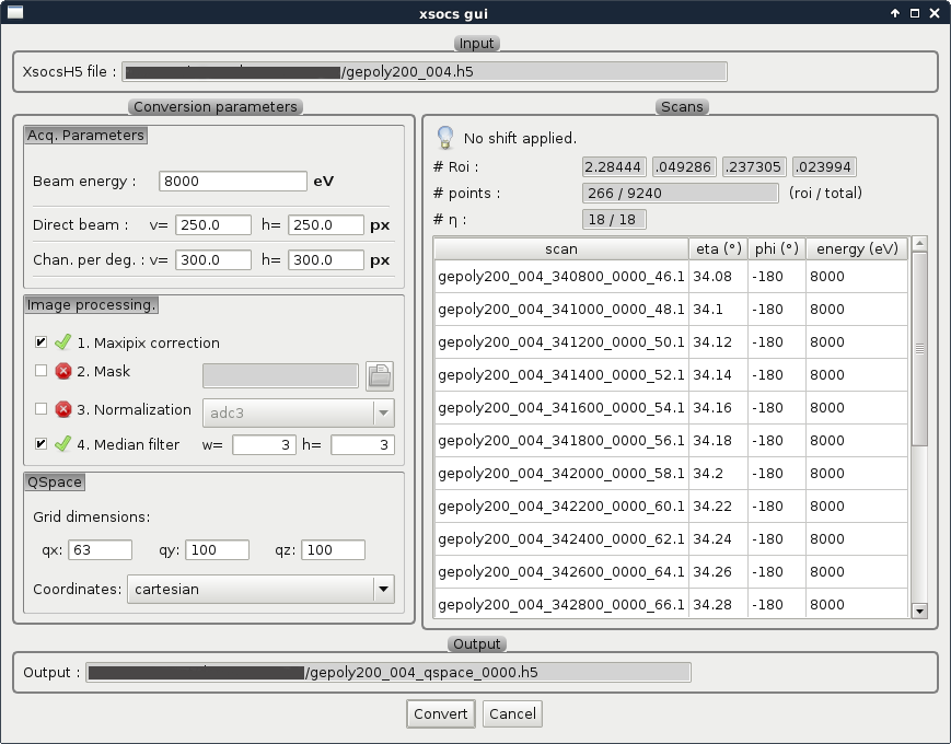
Fig. 5.1 Q space conversion dialog
This window lets you configure some parameters for the conversion from images to Q space:
The right panel allows to review the selected region of interest on the sample and the selected scan entries.
Click on Convert to start the conversion.
Once the conversion is done, a Q space item is added to the project tree. And the result is displayed in the Q sspace view.
Acq. Parameters
Parameter |
Description |
|---|---|
|
Energy of the beam, in eV |
|
Position in pixels of the direct beam on the detector |
|
Channels per degree |
Image Processing Parameters
All image processing steps are optional, check the corresponding check box to enable them.
Parameter |
Description |
|---|---|
|
Apply Maxipix detector module edges correction |
|
Select a mask image to apply on input images. The image MUST have the same size as input detector images. Non zero value in the mask image discard the corresponding pixels. |
|
Select the measurement to use for normalization. |
|
Set the size (width and height) of the median filter window. |
Q space Parameters
Parameter |
Description |
|---|---|
|
Number of bins for each dimension of the Q space histogram. |
|
Select the coordinate system of the QSpace histogram. Either Cartesian or Spherical. |
The conversion from Cartesian to Spherical coordinates is as follows:
Radius: \(\sqrt(qx^2 + qy^2 + qz^2)\)
Roll (Phi) in degrees: \(degrees(\pi/2 - arctan2(qz, qy))\)
Pitch (Theta) in degrees: \(degrees(\pi/2 - arccos(qx/radius)\)